Replacing Atari Jaguar CD Unit Laser Transport - page 4Noting the wires and removing the loom
Here you can now clearly see the connections for the lateral motor. You can also see the blue spot marking one of the motors connectors. Make a note of what wires are connected, on my unit they were:
Blue Wire
Lateral motor, No Spot
White Wire
Lateral motor, Spot
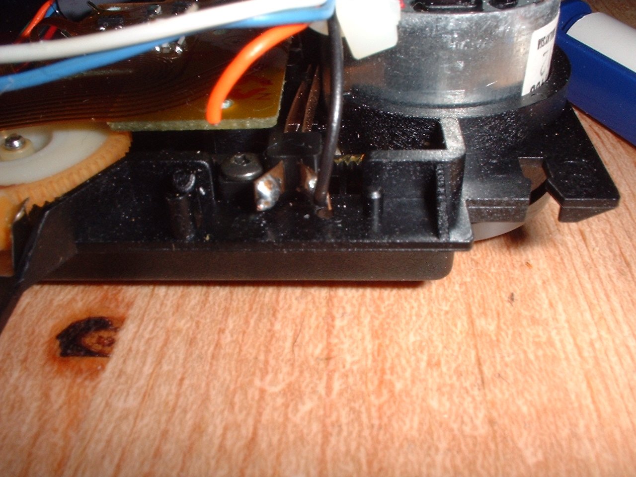
The above picture shows the wiring of what I have called the "Zero switch" (reports when the laser is at zero position, I know floppy drives have one, so why not! :) ), as you can see the orange wire has been broken off the solder join by some heavy handed lug (OOPS! see I told you they were delicate wires! :) ). I don't think the order of these wires is too critical, but better safe than sorry. On my unit they were as follows:
Black wire
Zero Switch, motor side
Orange wire
Zero Switch, non-motor side
Now we have all the wires locations noted, get desoldering them wires!
And here is the wireing loom completely removed from the old transport, ready to be fitted to the new.
And here we have it, our shiney new transport complete with wires ready to be put into the cradle. Take your time with the soldering, make sure you get good clean connections, and that they arn't brittle, we don't want it breaking just as we get really far in Myst now do we? :)