Replacing Atari Jaguar CD Unit Laser Transport - page 3Removing the PCB
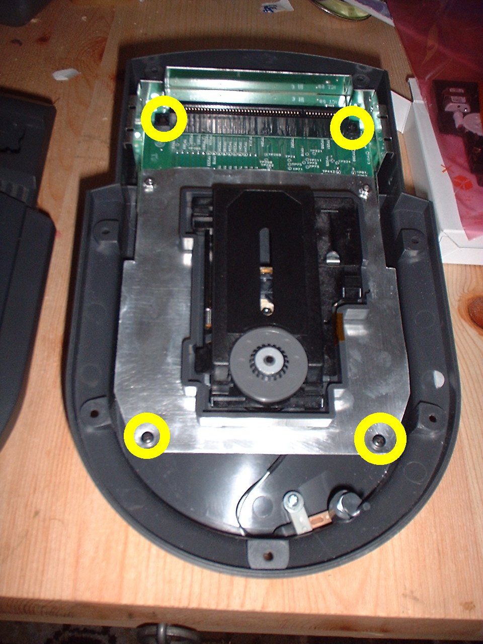
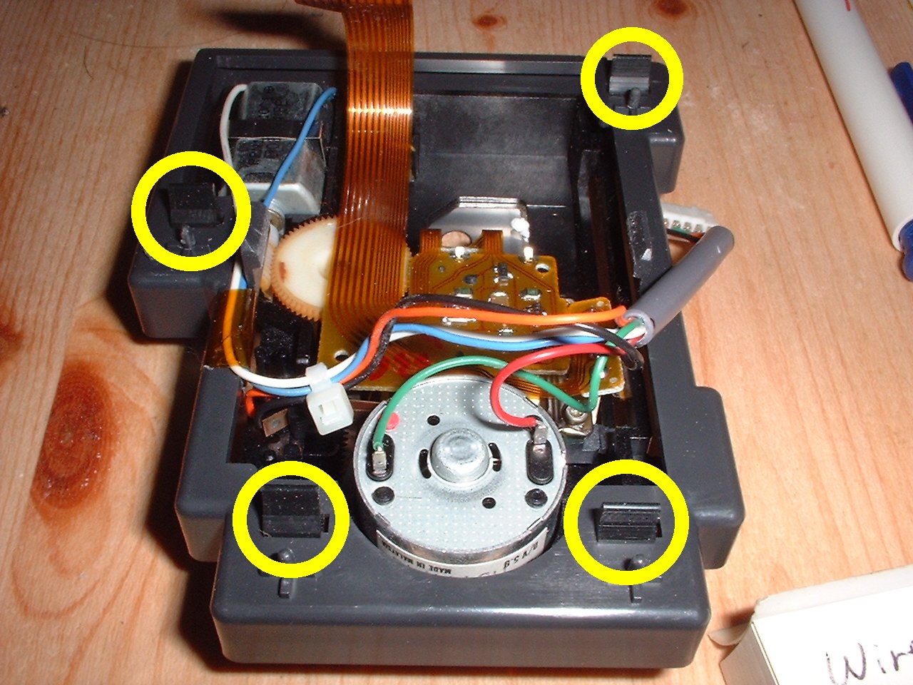
With the cover of you can now see the top of the current transport, the cartridge slot and a thin metal RF shield to protect the electronics from evil RF interference. The Transport is clipped onto the PCB, and also has it's connecting wires plugged into it, so we must remove the PCB to gain access to them. Remove the 4 screws holding the PCB to the bottom part of the casing, these screws are the same as the other 7, so no worries if you mix them up.
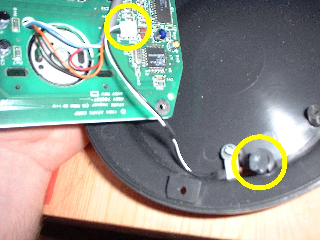
Once the screws are removed carefully lift the PCB out o fthe casing by it's edges, try not to touch the components on the PCB (evil static lurks everywhere!), you will notice that the CD Door closed switch is connected by a wire to the PCB, the wire is connected via a small plug, carefully remove it. Switch and plug are indicated on the picture. Now that it is disconnected, you can put the case to one side, try to keep it right side up otherwise the door closed switch may go walkies. Place the PCB on the table with the transport facing down
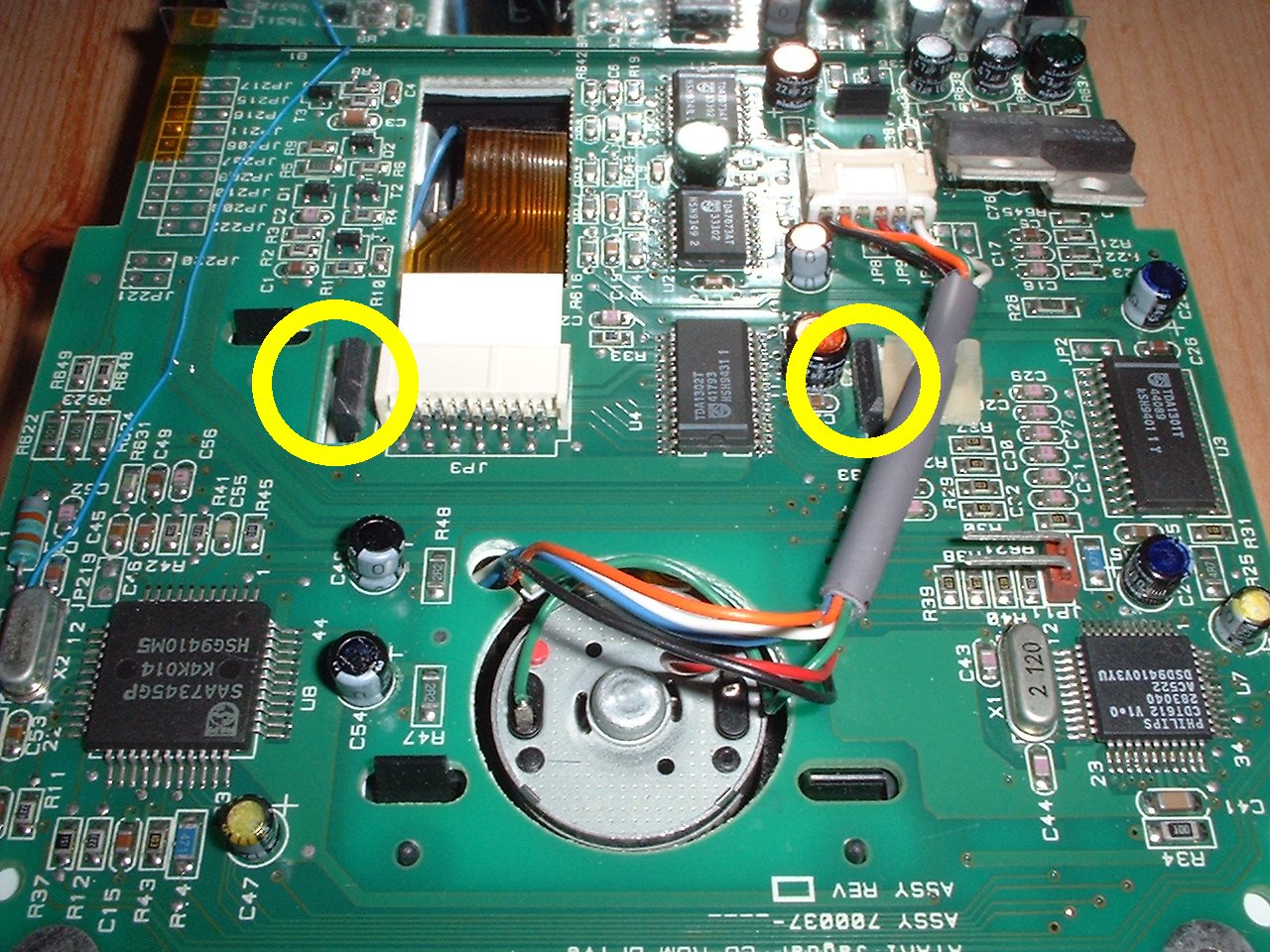
You can now get access to all the various connectors and clips to remove the current transport from the PCB. To remove the transport you have to prise the two marked clips off the PCB, the other clips are fairly loose and with a little carefull waggaling you can get the transport off. NOT YET THOUGH!. First we need to make a note of the wires we have. There are two connections to the transport, one via the film cable and another which connects via 6 coloured wires and a plug. We are interested in the coloured wires, when we re-connect these to the new transport they must be connected to the right places or we risk the Blue smoke being let out of the components. So before we go any further I recommend you get a pen and paper and note where the wires go. I don't know if all CD-Units have the same colour scheme so better safe than sorry.
Luckily all the motors have indication spots on them, so look for the coloured spot and use it as your reference.
Removing the current Transport
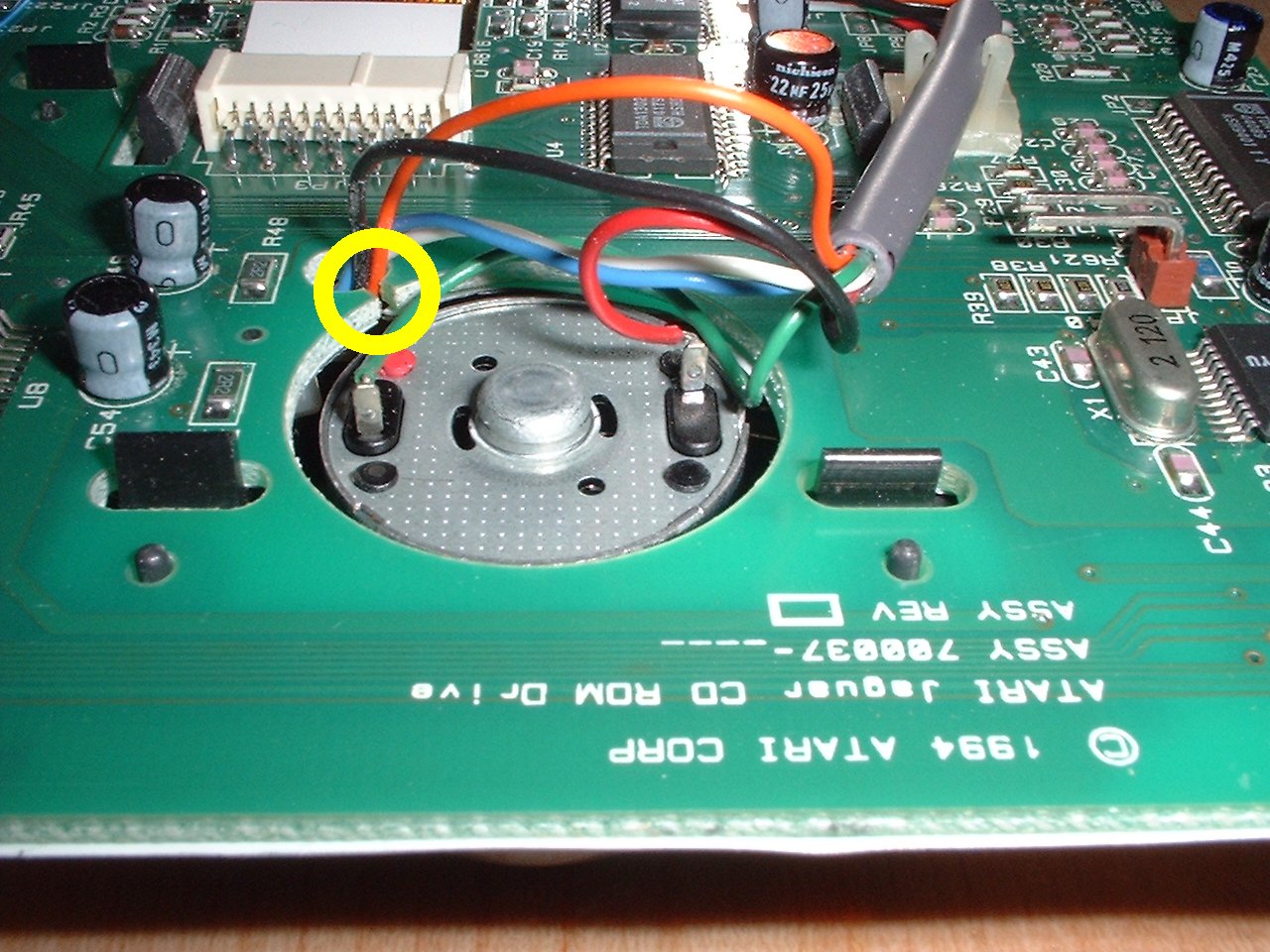
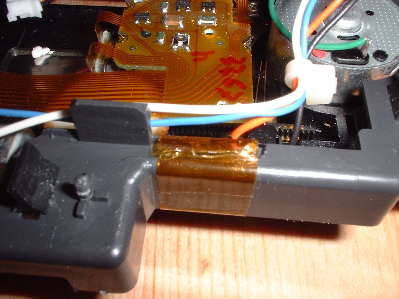
In the picture above you can clearly see a red spot next to the connector where the green wire attaches. Also notice the small notch indicated on the picture, you use this for slipping the wires out of when removing the transport. Make a note of the colour of the wires connecting to this motor before moving on (the wires are quite thin and therefore can easily be snapped off the motor). For my CD Unit, the colours were:
Green Wire
Spindle motor, Red spot
Red wire
Spindle motor, Black spot
Now carefully remove the film connector and the 6 wire plug from the PCB. Once they are disconnected carefully prise the clips appart holding the transport onto the PCB, and feed the 6 wires through the motor hole in the PCB. It is VERY important that you do not damage any of the clips or the thin RF shield when removing the transport. This is because these clips arn't part of the transport (you thought it looked a bit different didn't you), but infact are part of a cradle that holds the transport, obvioulsy we need this cradle in one piece so we can refit it with the new transport, so be careful.
Good, now you have removed the transport in it's cradle, the cradle is made of soft plastic so be gental with it, it bend easily. The cradle hoses the rubber suspension for the transport to help dampen some of the virations, but we need to get the transport out of there and finish noting where those wires connect, (the cradle obscures them a little, and leaving it on would make doing the soldering more difficult, plus we still need it for the new transport).
I have marked on the picture the mounts for the rubber suspension plugs, if you flip the unit over you will see where they hold the transport.
Before we remove the transport from the cable, check to see that none of the wires are attached to the cable, in my unit there was a piece of tape holding the wires for the lateral motor to the side of the cradle. Using the stanley knife carefully cut along the tape, being careful not to damage the thin motor wires. Remove the wires from the tape and away we go.
Now back to getting out of those suspension mounts. I tried to remove them from this side (underside as shown in above picture), but decided I would damage them before removing them. So to remove the transport from the cradle, we need to turn it over and get out our pointy/thin thing.
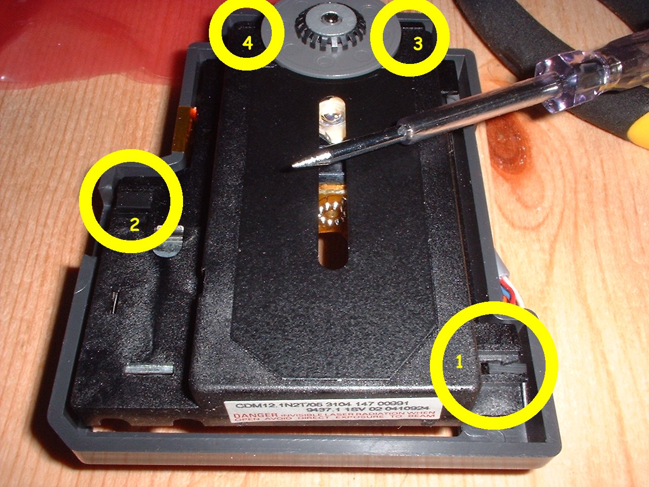
Here I have marked the locations of the 4 suspension mounts, also in the picture is the electrical tester that I used to carefully pry them off the transport with. I have numbered the mounts to indicate the order that I removed them. I think this order frees the transport up to more movement quickly making it easier to remove the next mount.
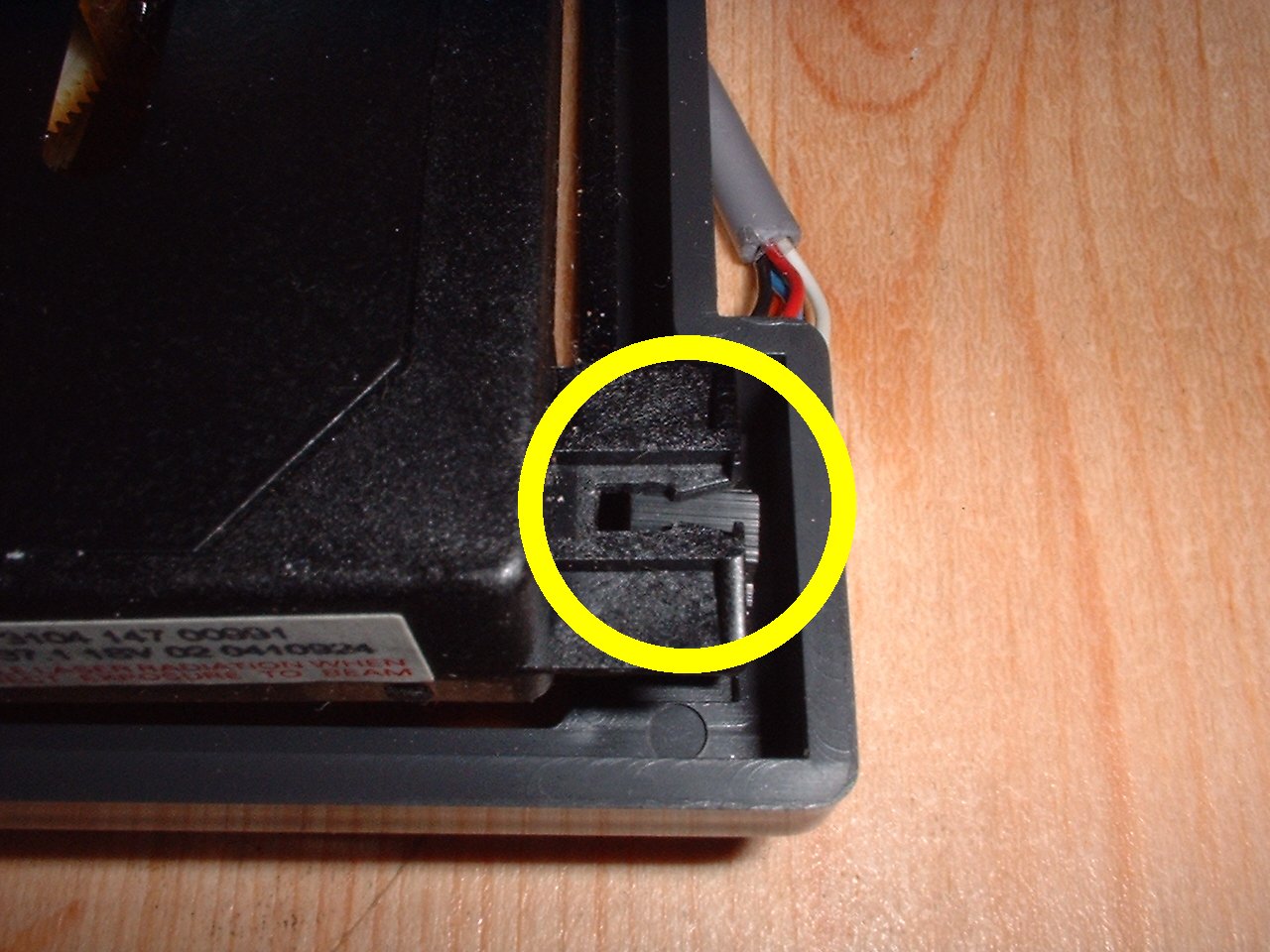
The above picture shows a closeup of one of the removed suspension mounts, you can see that the notch that they sit in on the transport has a lipped edge. To prise them out I carefully pushed the mount over this lip with the tester a small part at a time, rember we need these rubber suspension mounts, so try to not damage them.
And there we have it, the transport finally out of the CD-Unit and the cradle. Nearly time to get soldering, so probably worth plugging it in ready.